Including Kaushal Bodh Class 8 Solutions Project 4 and Class 8 Vocational Education Chapter 4 Home Automation Question Answer in your preparation can make learning more organized.
Class 8 Vocational Education Chapter 4 Question Answer
Kaushal Bodh Class 8 Chapter 4 Question Answer
What did I learn from others? [Page No. 104 – 105]
Question 1.
What are the precautions to be taken to protect the circuits from electricity fluctuations?
Answer:
The precautions to be taken to protect the circuits from electricity fluctuations are as follows
- Use a voltage stabiliser to maintain a constant voltage supply and protect the circuit from sudden voltage changes.
- Use a fuse or circuit breaker to prevent damage due to excess current flow.
- Use a regulated power supply instead of direct mains supply in electronic circuits.
- Ensure proper grounding (earthing) of the circuit to safely divert excess current.
Question 2.
Did you take help from experts or peers? What are the three most important things you learned about home automation?
Answer:
Yes, I took help from experts and peers while understanding home automation concepts and building circuits.
The three most important things I learned about home automation are
- Home automation uses sensors, microcontrollers, and programming to control devices automatically without manual switching.
- Sensors act as input devices that detect changes like light, temperature, motion, or moisture and send signals to the microcontroller.
- Automation systems work in a cycle of input, process, and output to perform tasks efficiently and save energy.
Think and Answer [Page No. 106]
Question 1.
Did you enjoy doing this project?
Answer:
Yes, this project was very enjoyable and engaging. Working with automation systems helped in understanding how everyday technology works. The hands-on experience of building circuits, connecting sensors, and programming made learning fun and interactive. It was satisfying to see the automation system respond correctly to different inputs and perform the intended actions.
Question 2.
What did you like most, and what would you do differently next time?
Answer:
What I liked most
- Creating a working automation system from scratch using simple components.
- Learning how sensors detect changes in the environment.
- Programming the microcontroller to control different devices.
- Testing the complete system and observing it work as planned.
What I would do differently next time
- Plan the circuit design more carefully before building.
- Test connections step by step to identify problems quickly.
- Use better quality components for more reliable results.
- Add more features to the system to make it more advanced.
Question 3.
Compare sensors and human sense organs. What can humans do with their senses that sensors cannot? What capabilities do humans have that automated systems do not?
For example, can systems be designed to respond to human emotions?
Answer:
The comparison between sensors and human sense
| Sensors | Human Sense Organs |
| Detect one specific type of input. | Detect multiple types of information at once. |
| Have a limited range of sensitivity. | Have a wide range of sensitivity and adaptation. |
Humans have the following capabilities
- Emotional intelligence such as empathy, feelings, and understanding others’ emotions.
- Creative thinking and problem-solving in new or unknown situations.
- Possibility of designing emotion-responsive systems.
Yes, systems can be designed to respond to human emotions using technologies like facial recognition, voice analysis, and emotion-detection software. However, these systems can only detect external signals of emotion and not truly understand or feel emotions like humans do.
Question 4.
Examples of jobs related to the work you did are automation engineer, technical support specialist, programmer, etc. What other jobs are related to the project? Look around, speak to people and write your answer. .
Answer:
Other jobs related to home automation include
- Electrical Engineer Designs and develops electrical systems and circuits.
- IoT (Internet of Things) Specialist Creates connected smart devices.
- Systems Administrator Manages and maintains automation systems.
- Network Engineer Sets up communication networks for smart homes.
- Product Designer Creates user-friendly interfaces for automation.
- Maintenance Technician Repairs and services automation equipment.
- Robotics Engineer Develops robots and automated machinery.
- Installation Specialist Installs automation systems in homes.

Home Automation Class 8 Question Answer
Activity 1: Exploring Automation in Our Surroundings
Purpose
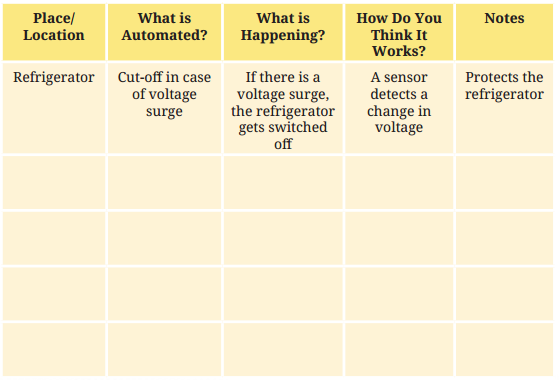
This activity will help students to observe and record automated systems found in everyday surroundings like classrooms, homes, vehicles, markets and media and understand how they work in everyday life.
Pre- Planning and Step
- A notebook and pen to record observations.
- Look carefully around your surroundings for things that work automatically.
- For each automated system you find, note: the place, what is automated, what is happening and how you think it works.
- Record all your observations in the table below
Observation Task
Question 1.
Why do you think automation is required?
Answer:
Automation is required to make work easier, faster and more accurate. It helps reduce human effort and saves time. Automated systems can perform repetitive or difficult tasks efficiently and also reduce the chances of errors.
Question 2.
What excites you most about the automated systems you observed?
Answer:
The most exciting part about automated systems is their ability to perform tasks independently with minimal human intervention.
Devices such as automatic doors, traffic lights, washing machines and smart home appliances make everyday life more convenient and comfortable.
Question 3.
Brainstorm ideas you may have to make life easier and free of drudgery (for example, to help your parents or complete any laborious activities). Let your imagination run free.
Answer:
I can imagine an automated cleaning robot that sweeps and mops the floor, a smart watering system for plants that works automatically when the soil is dry, and a machine that can sort clothes for washing. Such automated systems can help save time and reduce the workload of daily household chores.
Question 4.
Which automated system did you find most useful, and why?
Answer:
The automated system I found most useful is the motion sensor light because it saves electricity by turning ON and OFF automatically based on movement. It also adds convenience and reduces the need for manual operation in daily life.
Question 5.
What role do sensors and controllers play in the working of automated systems?
Answer:
Sensors and controllers play the following role in the working of automated systems
Role of Sensors
- Sensors detect changes in the environment such as light, temperature, or motion.
- They convert these changes into electrical signals for further processing.
Role of Controllers
- Controllers receive signals from sensors and process the information.
- They send commands to output devices to perform the required action automatically.
Kaushal Bodh Class 8 Home Automation Question Answer
Activity 2: Exploring circuits using a simulation platform
Purpose
This activity will help students to build and test simple electronic circuits using a simulation platform (e.g., Tinkercad) on a computer without physically using components.
Pre-Planning or Preparation
- A computer or laptop with internet access.
- Simulation Platform Tinkercad (www.tinkercad.com) or any equivalent platform.
- Search Keywords ‘Simulation for building circuits for beginners’ or ‘Tutorial for making electronic circuit+Tinkercad’.
- Make simulated circuits using the following component sets
Steps to Follow
Step 1: Draw the circuit you want to test.

Step 2: Open Tinkercad or any other simulation platform.
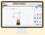
Step 3: Open workplace and place the required components.

Step 4: Make connections and test the circuit.
- Circuit A LED + 220-ft resistor + 9 V DC battery + switch
- Circuit B Buzzer + 220-ft resistor + 9 V DC battery + switch
Once done, design a few more circuits of your own and test them.
Observation
Record your observations below
1. Which software did you use?
_________________________________________________________
2. Did your circuits work? Try different components, such as other batteries and resistance values. Write down your observations of changes as a result of these trials.
_________________________________________________________
3. Draw the circuit diagrams you designed.

Question 1.
What is the advantage of using a simulation platform before building a real circuit?
Answer:
The advantage of using a simulation platform before building a real circuit is that it allows safe testing without real components. It helps in understanding how the circuit works, finding errors early, and improving the design before actual construction.
Question 2.
What happened when you increased the resistance value in your circuit? Did the LED glow brighter or dimmer?
Answer:
When the resistance value increased, the LED glowed dimmer because less current flowed through the circuit.
Question 3.
Why is it important to include a resistor in a circuit with an LED?
Answer:
A resistor is important because it limits the current flowing through the LED. Without a resistor, too much current may pass through the LED and damage or burn it out.
Question 4.
Which components were used to create Circuit A and Circuit B?
Answer:
The following components were used to create Circuit A and Circuit B
- Circuit A Components LED, 220-ohm resistor, 9V DC battery, switch.
- Circuit B Components Buzzer, 220-ohm resistor, 9V DC battery, switch.
Question 5.
What steps were followed to build and test the circuit on the simulation platform?
Answer:
The following steps were followed to build and test the circuit on the simulation platform
- The circuit was first drawn on paper.
- The simulation platform was opened on the computer.
- The workspace was opened and required components were placed.
- The connections were made according to the circuit design.
- The ‘Start Simulation’ option was clicked to test the circuit.
Activity 3: Building circuits using physical components
Purpose
This activity will help students to apply the circuit knowledge gained on the simulation platform by building real circuits using physical electronic components.
Pre-Planning or Preparation
- Collect a breadboard, jumper wires, 9V battery with clip, LED(s), buzzer, 220 Q resistor and switch.
- Be aware of optional projects such as an electronic rakhi, 3V DC motor with solar panel and a dancing doll using LED and DC motor.
- Search Keywords ‘DIY circuits for beginners’ or ‘Electronic projects for beginners’.
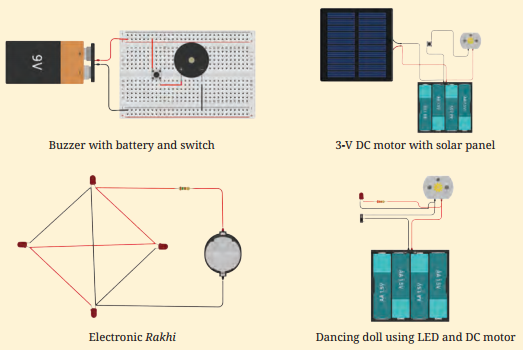
Creating Electronic items with Physical Components
Steps to Follow
- Choose one of the circuit designs you tested on the simulation platform.
- Gather the required physical components listed above.
- Place components on the breadboard according to your circuit diagram.
- Connect the components using jumper wires, following the circuit diagram carefully.
- Connect the battery last. Observe what happens.
- If it does not work, recheck all connections and the polarity of the LED.
Question 1.
Which circuit did you build?
Answer:
I built a simple LED circuit using a 9V battery, a 220 £2 resistor and a switch.
Question 2.
Which components did you use? Write their specifications.
Answer:
The components I have used and their specifications are as follows
- LED (Light Emitting Diode): A semiconductor device that emits light when current flows through it It is used as an indicator in the circuit.
- Resistor – 220 O resistor: A passive component used to limit the flow of current and protect the LED from damage.
- Battery – 9 V DC battery: A portable power source that supplies direct current to the circuit.
- Switch: A mechanical device used to open or close the circuit and control the flow of current
- Breadboard and jumper wires: A breadboard is used for temporary circuit connections without soldering, and jumper wires are used to connect different components on the breadboard.
Question 3.
Draw circuit diagrams of the circuits you designed
Answer:
Circuit Diagram (LED Circuit)
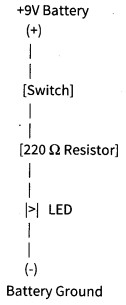
Explanation: Current flows from the positive terminal of the battery -» switch -»resistor -> LED back to the negative terminal, completing the circuit and making the LED glow.
Question 4.
Why is it important to follow the circuit diagram while connecting components?
Answer:
It is important to follow the circuit diagram while connecting components because it ensures correct connections, proper flow of electricity, and safe operation of the circuit.
It also helps in avoiding errors, preventing damage to components, and making the circuit work efficiently.
Question 5.
What precautions should be taken while connecting the battery and checking the circuit?
Answer:
The following precautions should be taken white connecting the battery and checking the circuit
- Ensure correct polarity while connecting the battery to avoid damage to components.
- Connect the battery only after completing all other connections properly.
- Check all connections carefully to avoid short circuits.
- Switch off the power supply immediately if any overheating or unusual behaviour is observed.
Activity 4: Making the circuit smart
Purpose
This activity will help students to connect an Arduino Uno microcontroller, programme it using Arduino and control an LED to make a manually controlled circuit into a smart and programmable one.
Pre-Planning or Preparation
- Collect Arduino Uno microcontroller board, 5mm LED, 220-ohm resistor, breadboard, jumper wires.
- Arrange USB cable (Arduino to computer).
- Prepare Computer with Arduino IDE installed (download from: www.arduino.ee).
Steps to Follow
- Search ‘Tutorial + beginner + Arduino Uno’ to understand pin connections.
- Connect the LED (with 220-ohm resistor) to digital pin 13 and GND on the Arduino with your teacher’s help.
- Download and install Arduino IDE from the official Arduino website.
- Open Arduino IDEGo to FileExamples → Basics → Blink. This opens the Blink programme.
- Connect the Arduino board to your computer using the USB cable.
- Go to Tools Port → select Arduino Uno COM port. Then click the Upload arrow.
- The onboard LED should blink every second.
- Change the ‘delay’ value in the code (e.g., from 1,000 to 500) and upload again. Observe the change in blinking speed.
- Try turning LED ON/OFF and adding multiple LEDs to create blinking patterns.
Question 1.
What is a microcontroller? How is it different from a regular switch in a circuit?
Answer:
A microcontroller is a small programmable device that controls electronic components by following instructions in a program. It can perform multiple automatic tasks like reading sensors and controlling outputs.
The difference between a microcontroller and a regular switch is as follows
| Microcontroller | Switch |
| Programmable and performs automatic tasks. | Manually operated device. |
| Can control multiple components. | Only turns a circuit ON or OFF. |
| Works using a program. | No programming required. |
Question 2.
What is a programme? Why do we need to give a programme to the microcontroller?
Answer:
A programme is a set of instructions written in a programming language that tells the microcontroller what actions to perform.
We need to give a programme to the microcontroller so that it can control the circuit and perform tasks automatically according to the instructions.
Question 3.
What is the role of the ‘delay’ command in the Arduino Blink programme?
Answer:
The role of the ‘delay’ command in the Arduino Blink programme is as follows
- It pauses the programme for a specific amount of time in milliseconds.
- It controls how long the LED stays ON or OFF.
- It helps create a visible blinking effect by adding time gaps between ON and OFF states.
- It allows the user to adjust the blinking speed by changing the delay value.
Question 4.
What does GND mean, and why is it important in a circuit?
Answer:
GND stands for Ground. It is the reference point in a circuit and provides a return path for electric current to flow back to the power source.
It is important because without a proper ground connection, the circuit will not work correctly.
Question 5.
What happens when the ‘delay’ value in the program is changed, and how does it affect the LED?
Answer:
When the ‘delay’ value in the program is changed, the time interval between turning the LED ON and OFF also changes. A smaller delay makes the LED blink faster, while a larger delay makes it blink slower.
Activity 5: Exploring automation cycle
Purpose
This activity will help students to understand and apply the Input-Process-Output cycle of automation by designing and building a smart light system using a PIR motion sensor and Arduino Uno.
Pre-Planning or Preparation
- You need to arrange microcontroller (Arduino Uno), PIR motion sensor, 5mm LED, 220 Cl resistor, breadboard, jumper wires, USB cable, computer with Arduino IDE installed.
- Search ‘Tutorial + automated + streetlight + Arduino Uno’ for circuit diagram and code.
Steps to Follow
- Connect the PIR sensor’s VCC to 5V pin, GND to GND pin and OUT pin to digital pin 2 on Arduino.
- Connect the LED (with 220-ohm resistor) to digital pin 13 and GND.
- Open Arduino IDE and write/modify the code: if PIR detects motion -* turn LED ON; else -»turn LED OFF.
- Upload the programme to the Arduino board.
- Test the circuit: move your hand in front of the PIR sensor and observe the LED.
- Now design your own automation system of your choice using the same steps.
Observation
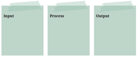
Fill in the Input-Process-Output table for each system
1. Automatic Water Sprinkler System
2. An Automation Device of Your Choice

Question 1.
Did your circuit work the first time? If not, please write down what you need to fix.
Answer:
The circuit did not work perfectly at first. After checking the connections, I corrected the wiring of the LED and ensured the PIR sensor pins were connected properly to 5 V, GND and pin 2.
After fixing the connections and uploading the code again, the circuit worked correctly.
Question 2.
What is the role of the PIR motion sensor in the smart light system?
Answer:
The role of the PIR motion sensor in the smart light system is as follows
- It detects motion by sensing infrared radiation from humans or animals.
- It acts as an input device by sending signals to the microcontroller.
- It helps in automatic operation of the system without manual control.
- It improves energy efficiency by activating the light only when motion is detected.
Question 3.
What happens to the LED when motion is detected and when no motion is detected?
Answer:
When motion is detected, the LED turns ON as the sensor sends a signal to the microcontroller. When no motion is detected, the LED turns OFF, as no signal is sent, and the system remains inactive.
Question 4.
What are the input, process and output in the smart light system you built?
Answer:
The input, process and output in the smart light system are as follows
- Input: The PIR motion sensor detects movement and sends a signal.
- Process: The Arduino microcontroller processes the signal and decides whether to turn the LED ON or OFF.
- Output: The LED turns ON when motion is detected and turns OFF when no motion is detected.
Question 5.
Why is the Input-Process-Output cycle important in automation systems?
Answer:
The Input-Process-Output cycle is important in automation systems because it helps the system work automatically and efficiently. It ensures that data is collected through input, processed correctly, and the required action is performed as output without manual intervention.
Activity 6: Make your own automation system using a microcontroller
Purpose
This activity will help students to independently design, build, programme and test a complete automation system of their choice using a microcontroller and sensors.
Pre-Planning
- Before building your system, plan the input, process and output clearly.
- Choose a microcontroller suitable for your project.
- Look up tutorials online for reference code — then modify it to suit your project.
- Test your circuit on a breadboard first before making it permanent.
- To make the circuit independent of a computer, package it with a Lithium-Ion battery and DC connector cable.
- Use a 3D-printed casing or any available material to protect and house your circuit.
Search ideas online using
- Instructions + automatic plant watering system + using Arduino
- DIY + automatic obstacle detecting system + using Arduino
- DIY + beginners + automatic fire alarm system + using Arduino • DIY + automatic gate opening system
- DIY + automatic theft detection alarm system • Instruction + smart fan + Arduino
Question 1.
What automation system do you want to make? What is the process?
Answer:
I want to make an Automatic Plant Watering System using Arduino. In this system, a soil moisture sensor checks the moisture level of the soil.
Process
If the soil becomes dry, the Arduino microcontroller processes the signal and automatically turns on a small water pump to water the plant.
When the soil becomes sufficiently moist, the pump turns off automatically.
Question 2.
Write about the Input, Process and Output of your project.
Answer:
The input, process and output of project is as follows
| Input (Sensing) | Process (Decision Making) | Output (Action) |
| Soil moisture sensor detects the moisture level of the soil. | Arduino processes the sensor signal and checks whether the soil is dry or wet. | If soil is dry→ water pump turns ON. If soil is wet → pump remains OFF. |
Question 3.
What are the materials required by the automation system?
Answer:
Materials required by the automation system are as follows
- Arduino Uno microcontroller
- Soil moisture sensor
- Water pump
- Breadboard
- Jumper wires
- 220 Ω resistor
- LED (for indication)
- Lithium-Ion battery or power supply
- DC connector cable
Question 4.
Did you modify the code received from other sources? Mention the site, the information you got, and the modification you made.
Answer:
Yes, I’ve modified the code from other sources. I referred to tutorials available on Arduino official website and YouTube tutorials for Arduino projects. I learned how to connect the soil moisture sensor and control the water pump.
I modified the code by adjusting the moisture threshold value so that the pump turns on only when the soil becomes very dry.
Question 5.
Draw the block diagram/sketch/circuit of your automation system.
Answer:

Question 6.
Did your automation system work as per the plan? If not, what are the reasons? What will you change next time?
Answer:
The automation system did not work, properly at first as planned. The reasons are as follows
- Incorrect or loose connections between components.
- Improper sensor calibration or wrong threshold values in the code.
Next time, I will carefully check all wiring before switching ON the circuit and adjust the sensor calibration more accurately to ensure proper and reliable functioning of the system.