Students can access the CBSE Sample Papers for Class 12 Physics with Solutions and marking scheme Set 1 will help students in understanding the difficulty level of the exam.
CBSE Sample Papers for Class 12 Physics Set 1 with Solutions
Time : 3 Hours
Maximum Marks: 70
General Instructions :
- There are 33 questions in all. All questions are compulsory.
- This question paper has five sections: Section A, Section B, Section C. Section D and Section E.
- Air the sections are compulsory.
- Section A contains sixteen questions, twelve MCQ and four Assertion-Reasoning based questions of 1 mark each, Section B contains five questions of two marks each, Section C contains seven questions of three marks each, Sections D contains two case study-based questions of four marks each and Section E contains three long answer questions of five marks each.
- There is no overall choice. However, an internal choice has been provided in one question in Section B, one question in Section C, one question in each CBQ in Section D and all three questions in Section E. You have to attempt only one of the choices in such questions.
- Use of calculators is not allowed.
- You may use the following values of physical constants wherever necessary
(i) c = 3 ×10⁸ m/s
(ii) me = 9.1 × 10⁻³¹ kg
(iii) e = 1.6 × 10⁻¹⁹ C
(iv) μ0= 4π × 10-17 TmA-1
(v) h = 6.63 × 10⁻³⁴ Js
(vi) ε0 = 8.854 ×10⁻¹² C2N-1m-2
(vii) Avogadro’s number = 6.023 × 10²³ per gram mole
Section – A
Question 1.
Which of the following is not the property of an equipotential surface?
(a) They do not cross each other.
(b) The work done in carrying a charge from one point to another on an equipotential surface is zero.
(c) For a uniform electric field, they are concentric spheres.
(d) They can be imaginary spheres.
Answer:
(c) For a uniform electric field, they are concentric spheres.
Explanation: For uniform electric field, equipotential surfaces are plane.
Question 2.
An electric dipole placed in an electric field of intensity 2 × 10⁵ N/C at an angle of 30° experiences a torque equal to 4 Nm. The charge on the dipole of dipole length 2 cm is:
(a) 7 μC
(b) 8 mC
(c) 2 mC
(d) 5 mC
Answer:
(c) 2 mC
Explanation:
t = pE sin θ
x = ql E sin θ
\(\frac{\tau}{l E \sin \theta}=q\)
\(\frac{4}{2 \times 10^5 \times 2 \times 10^{-2} \sin 30^{\circ}}=q\)
q = 2 × 10⁻³ C = 2 mC
t = Torque
E = Electric field
θ = Angle between dipole moment and electric field
q = Charge on dipole
![]()
Question 3.
‘A metallic plate exposed to white light emits electrons. For which of the following colours of light, the stopping potential will be maximum?
(a) Blue
(b) Yellow
(c) Red
(d) Violet
Answer:
(d) Violet
Explanation: Greater the frequency greater the stopping potential violet light has the greatest frequency.
Question 4.
When alpha-particles are sent through a thin gold foil, most of them go straight through the foil, because:
(a) alpha-particles are positively charged
(b) the mass of an alpha-particle is more than the mass of an electron
(c) most of the part of an atom is empty space
(d) alpha-particles move with high velocity
Answer:
(c) most of the part of an atom is empty space
Explanation: As most mass of atom is concentrated in tiny space called nucleus most of atom is empty space.
Question 5.
An electron is moving along positive X-axis in a magnetic field which is parallel to the positive Y-axis. In what direction will the magnetic force be acting on the electron?
(a) Along -X axis
(b) Along -Z axis
(c) Along +Z axis
(d) Along -Y axis
Answer:
(b) Along -Z axis
Explanation: Using Flemings left hand rule. Thumb points towards force. Index finger points towards magnetic field and middle finger point opposite to electron velocity as that is the direction of current. Thumb points in negative Z-axis.
Question 6.
The relative permeability of a substance X is slightly less than unity and that of substance Y is slightly more than unity, then:
(a) X is paramagnetic and Y is ferromagnetic
(b) X is diamagnetic and Y is ferromagnetic
(c) X and Y both are paramagnetic
(d) X is diamagnetic and Y is paramagnetic
Answer:
(d) X is diamagnetic and Y is paramagnetic
Explanation: As μr = 1 + xm
as relative permeability is equal to one plus magnetic susceptibility (xm). xm as is negative for diamagnetic substances and slightly positive for paramagnetic substances.
μr >1 for paramagnetic substances
μr <1 for diamagnetic substances
![]()
Question 7.
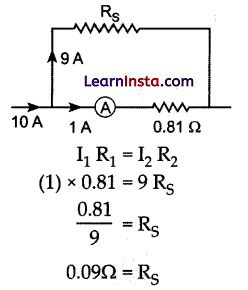
An ammeter of resistance 0.81 ohm reads up to 1 A. The value of the required shunt to increase the range to 10 A is:
(a) 0.9 ohm
(b) 0.09 ohm
(c) 0.03 ohm
(d) 0.3 ohm
Answer:
(b) 0.09 ohm
Explanation:
Question 8.
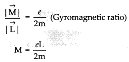
An electron with angular momentum L moving around the nucleus has a magnetic moment given by:
(a) eL/ 2m
(b) eL/3m
(c) eL /4m
(d) eL/m
Answer:
(a) eL/ 2m
Explanation:
Question 9.
The large scale transmission of electrical energy over long distances is done with the use of transformers.
The voltage output of the generator is stepped-up because of :
(a) reduction of current
(b) reduction of current and voltage both
(c) power loss is cut down
(d) both (a) and (c)
Answer:
(d) both (a) and (c)
![]()
Question 10.
The diagram below shows the electric field \((\overrightarrow{\mathrm{E}})\) and magnetic field \((\overrightarrow{\mathrm{B}})\) components of an electromagnetic wave at a certain time and location.

The direction of the propagation of the electromagnetic wave is:
(a) perpendicular to \((\overrightarrow{\mathrm{E}})\) and \((\overrightarrow{\mathrm{B}})\) and out of plane of the paper
(b) perpendicular to \((\overrightarrow{\mathrm{E}})\) and \((\overrightarrow{\mathrm{B}})\) and into the plane of the paper
(c) parallel and in the same direction as \((\overrightarrow{\mathrm{E}})\)
(d) parallel and in the same direction as \((\overrightarrow{\mathrm{B}})\)
Answer:
(a) perpendicular to \((\overrightarrow{\mathrm{E}})\) and \((\overrightarrow{\mathrm{B}})\) and out of plane of the paper
Explanation: The direction of propagation of electromagnetic wave points towards \((\overrightarrow{\mathrm{E}})\) × \((\overrightarrow{\mathrm{B}})\) which using right hand thumb rule. Which points out of plane of paper.
Question 11.
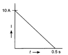
In a coil of resistance 100 Ω a current is induced by changing the magnetic flux through it. The variation of current with time is as shown in the figure. The magnitude of change in flux through coil is:
(a) 200 Wb
(b) 275 Wb
(c) 225 Wb
(d) 250 Wb
Answer:
(d) 250 Wb
Explanation:
\(e=\frac{\Delta \phi}{\Delta t}\) Rate of change of flux
\(\frac{e}{\mathrm{R}}=\mathrm{I}=\frac{\Delta \phi}{\Delta t} \mathrm{R}\)
\(\mathrm{I} \Delta t=\frac{\Delta \phi}{\Delta t}=\) Area under I – t graph, R = 100Q
Change in flux \(\Delta \phi=\mathrm{RI} \Delta t=100 \times \frac{1}{2} \times 10(0.5)\)
\(\Delta \phi=250 \mathrm{~Wb}\)
Question 12.
The energy of an electron in nth orbit of hydrogen atom is En = – 13.6/n2 eV. The negative sign of energy indicates that:
(a) electron is free to move.
(b) electron is bound to the nucleus.
(c) kinetic energy of electron is equal to potential energy of electron.
(d) atom is radiating energy.
Answer:
(b) electron is bound to the nucleus.
Explanation: Electron is bound to nucleus threfore, total energy is negative.
For Questions 13 to 16, two statements are given one labelled Assertion (A) and other labelled
Reason (R). Select the correct answer to these questions from the options as given below:
(a) If both Assertion and Reason are true and Reason is correct explanation of Assertion.
(b) If both Assertion and Reason are true but Reason is not the correct explanation of Assertion.
(c) If Assertion is true but Reason is false.
(d) If both Assertion and Reason are false.
![]()
Question 13.
Assertion (A): For the radiation of a frequency greater than the threshold frequency, photoelectric current is proportional to the intensity of the radiation.
Reason (R): Greater the number of energy quanta available, greater is the number of electrons absorbing the energy quanta and greater is number of electrons coming out of the metal.
Answer:
(a) If both Assertion and Reason are true and Reason is correct explanation of Assertion.
Question 14.
Assertion (A): Putting p-type semiconductor slab directly in physical contact with n-type semiconductor slab cannot form the pn junction.
Reason (R): The roughness at contact will be much more than inter-atomic crystal spacing and continuous flow of charge carriers is not possible.
Answer:
(a) If both Assertion and Reason are true and Reason is correct explanation of Assertion.
Question 15.
Assertion (A): An electron has a higher potential energy when it is at a location associated with a negative value of potential and has a lower potential energy when at a location associated with a positive potential.
Reason (R): Electrons move from a region of higher potential to a region of lower potential.
Answer:
(c) If Assertion is true but Reason is false.
Explanation: Electrons move from lower potential to higher potential.
Question 16.
Assertion (A): Propagation of light through an optical fibre is due to total internal reflection taking place at the core-cladding interface.
Reason (R): Refractive index of the material of the cladding of the optical fibre is greater than that ofthe core.
Answer:
(c) If Assertion is true but Reason is false.
Explanation: Core has a greater refractive index than cladding.
Section – B
Question 17.
(a) Name the device which utilizes unilateral action of a pn diode to convert a.c. into d.c.
(b) Draw the circuit diagram of full wave rectifier.
Answer:
(a) Rectifier
(b) Circuit diagram
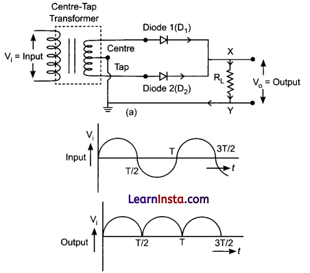
Question 18.
The wavelength λ of a photon and the de-Broglie wavelength of an electron of mass m have the same value. Show that the energy of the photon is 2λ mc/h times the kinetic energy of the electron, where c and h have their usual meanings.
Answer:
\(\lambda=\frac{h}{p}\) (p = momentum of electron)
Ee = Kinetic energy of electron = \(\frac{p^2}{2 m}=\frac{h^2}{\lambda^2 2 m}\)
Ep = Energy of photon = \(\frac{h c}{\lambda}\)
\(\frac{\mathrm{E}_p}{\mathrm{E}_e}=\frac{h c}{\lambda} \div \frac{h^2}{\lambda^2 2 m}=\frac{h c}{\lambda} \frac{\lambda^2 2 m}{\lambda^2}=\frac{c \lambda 2 m}{h}\)\(\mathrm{E}_p=\frac{2 m c \lambda}{h} \mathrm{E}_e\) Hence proved.
![]()
Question 19.
A ray of monochromatic light passes through an equilateral glass prism in such a way that the angle of incidence is equal to the angle of emergence and each of these angles is 3/4 times the angle of the prism. Determine the angle of deviation and the refractive index of the glass prism.
Answer:
For equilateral prism
A = 60° = Angle of prism
i = e = condition for minimum deviation
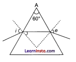
\(i=\frac{3}{4} \mathrm{~A}=45^{\circ}\)
\(\begin{aligned}
& \delta_{\min }=i+e-\mathrm{A}=45^{\circ}+45^{\circ}-60^{\circ} \\
& \delta_{\min }=30^{\circ}
\end{aligned}\)
n = Refractive index
Question 20.
A heating element using nichrome connected to a 230 V supply draws an initial current of 3.2 A which settles after a few seconds to a steady value of 2.8 A. What is the steady temperature of the heating element if the room temperature is 27.0 °C and the temperature coefficient of resistance of nichrome is 1.70 × 10⁻⁴ °C-1 ?
Answer:
Using Ohm’s law
V =IR
R0 = Initial resistance
\(\mathrm{R}_0=\frac{\mathrm{V}}{\mathrm{I}_0}=\frac{230}{3.2}=71.875 \mathrm{~W}\)
Rs = Steady state resistance
Rs = \(\mathrm{R}_{\mathrm{S}}=\frac{\mathrm{V}}{\mathrm{I}_{\mathrm{S}}}=\frac{230}{2.8}=82.142 \Omega\)
Rs = R0 [1 + ∝ ΔT]
Rs=R0[1+ ∝ (Ts-T0)]
82.142 = 71.875 [1 + 1.7 × 10⁻⁴ (Ts– 27°C)]
1.1428 = 1 + 1.7 × 10⁻⁴ (Ts– 27°C)
Ts = 867.2°C
Steady state temperature of heating coil.
![]()
Question 21.
Show that the least possible distance between an object and its real image in a convex lens is 4f where f is the focal length of the lens.
OR
In an astronomical telescope in normal adjustment a straight black line of length L is drawn on the objective lens. The eyepiece forms a real image of this line whose length is l. What is the angular magnification of the telescope?
Answer:
Let d be the distance between object and image for real image for motion.
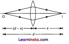
Let x be image distance = v
-(d- x) is object distance = u
using lens formula
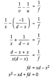
here x1 and x2 are roots of equation
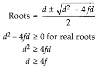
OR
f0 = focal length of objective
fe = focal length of eyepiece
d = length of telescope
d = f0 + fe [length of telescope in normal adjustment]
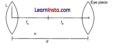
For line drawn on objective
u = object distance
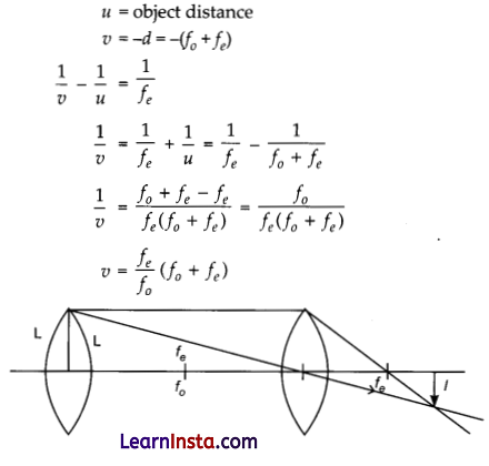
Magnification = \(\frac{v}{u}=-\frac{l}{\mathrm{~L}}=\frac{f_e\left(f_0+f_e\right)}{f_0\left(f_0+f_e\right)}\)
\(\frac{l}{\mathrm{~L}}=\frac{f_e}{f_o}\)
\(\frac{f_0}{f_e}=\frac{\mathrm{L}}{l}\)
Angular magnification of lens = \(\frac{f_0}{f_e}=\frac{\mathrm{L}}{l}\)
Section – C
Question 22.
A given coin has a mass of 3.0 g. Calculate the nuclear energy that would be required to separate all the neutrons and protons from each other. For simplicity assume that the coin is entirely made of \(\begin{aligned}& 63 \\& 29\end{aligned}\) Cu atoms (of mass 62.92960 u).
(Given mp = 1.007825 u and mn = 1.008665 u.)
OR
Draw the graph showing the variation of binding energy per nucleon with mass number. Write two inferences which can be drawn from this graph.
Answer:
Mass of coin is 3.0g
No. of moles of \(\begin{aligned}& 63 \\& 29\end{aligned}\) C in coin= \(\frac{\text { Mass }}{\text { Atomic mass }}\)
\(=\frac{3}{62.92960}=0.0476 \mathrm{~mole}\)No. of atoms = 0.0476 NA = 0.047 × 6.022 × 1023 atom
= 2.86 × 10²² atoms
Each atom has 29 protons and 34 neutrons
Thus mass defect
Δm = 29 × 1.00783 + 34 × 1.00867- 62.92960 = 0.59225m
Nuclear energy required for one atom = 0.59225 x 931.5 MeV
= 0.5225 × 931.5 × 2.86 × 1022 McV
= 1.58 × 1025 MeV
OR
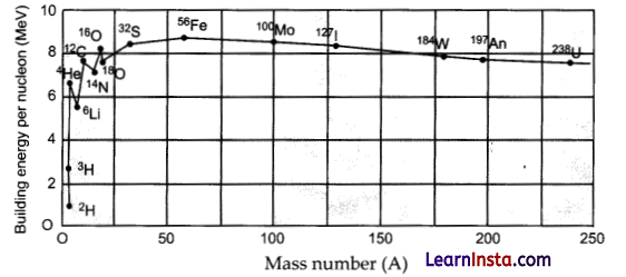
The binding energy per nucleon as a function of mass number.
(i) The binding energy per nucleon, Ebn, is practically constant, i.e., practically independent of the atomic number for nuclei of middle mass number (30 < A < 170). The curve has a maximum of about 8.75 MeV for A = 56 and has a value of 7.6 MeV for A = 238.
(ii) Ebn is lower for both light nuclei (A < 30) and heavy nuclei (A > 170).
We can draw some conclusions from these two observations:
(i) The force is attractive and sufficiently strong to produce a binding energy of a few MeV per nucleon.
(ii) The constancy of the binding energy in the range 30 < A < 170 is a consequence of the fact that the nuclear force is short-ranged.
![]()
Question 23.
Charges (+q) and (-q) are placed at the points A and B respectively which are a distance 2 L apart. C is the midpoint between A and B. What is the work done in moving a charge + Q along the semicircle CRD.
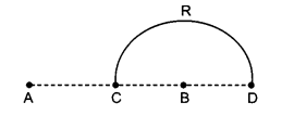
Answer:
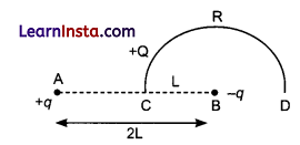
Work done = ΔV = Change in potential energy
ΔU = Q (Vf— Vi)
ΔU = Q (Final potential-initial potential)
ΔU = Q (VD-VC)
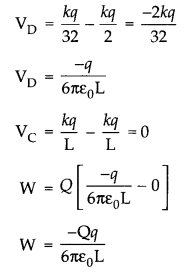
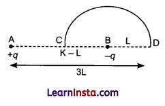
Question 24.
The total energy of an electron in the first excited state of the hydrogen atom is about- 3.4 eV.
(a) What is the kinetic energy of the electron in this state?
(b) What is the potential energy of the electron in this state?
(c) Which of the answers above would change if the choice of the zero of potential energy is changed?
Answer:
(a) K.E. = -T.E. = -(3.4 eV)
Kinetic energy = 3.4 eV
(b) RE. = 2T.E. = -6.8 eV
Potential energy = -6.8 eV
(c) P.E. (Potential energy) will change with change in choice of zero potential. And value of total energy will also change.
![]()
Question 25.
A wire of uniform cross-section and resistance 4 ohm is bent in the shape of square ABCD. Point A is connected to a point P on DC by a wire AP of resistance 1 ohm. When a potential difference is applied between A and C, the points B and P are seen to be at the same potential. What is the resistance of the part DP?
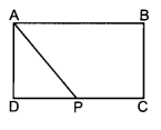
Answer:
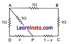
Let x ohm be resistance of DPA.
Resistance in section AP
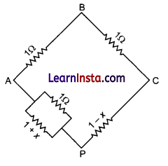
\(\frac{1}{1}+\frac{1}{1+x}=\frac{1}{\mathrm{R}_{\mathrm{net}}}\)
As B and P have same potential
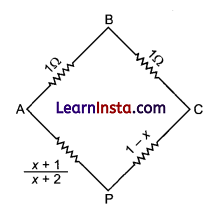
\(\frac{1}{1}=\frac{x+1}{(x+2) 1-x}\)
(x + 2)(1-x) -x +1
x + 2-x²-2x =x + 1
x² + 2x-1 =0
x = √2 – 1 ohm
Question 26.
The given figure shows a long straight wire of a circular cross-section (radius a) carrying steady current I. The current I is uniformly distributed across this cross-section. Calculate the magnetic field in the region r < a and r > a.
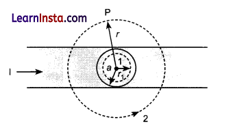
Answer:
For r <a
We draw an amperian loop labelled 1.
Current in wire = I
J = Current density in wire = \(\frac{\mathrm{I}}{\pi a^2}\)
Current through amperial loop = jπr²
Using Ampere circuital law,
\(\begin{aligned}
& \int \mathrm{B} \cdot d l=\mathrm{I} \mu_0 \\
& \text { В } 2 \pi r=\frac{\mathrm{I} r^2}{a^2} \mu_0
\end{aligned}\)
\(\mathrm{B}=\frac{\mu_0}{2 \pi} \frac{\mathrm{I}(r)}{a^2}\)
B ∝ r
For r < a
For r > a use amperian loop labelled 2
\(\begin{aligned}
\int \mathrm{B} . d l & =\mu_0 \mathrm{I} \\
\mathrm{B}(2 \pi r) & =\mu_0 \mathrm{I}
\end{aligned}\)
\(\mathrm{B}=\frac{\mu_0 \mathrm{I}}{2 \pi r} \mathrm{~B} \propto \frac{1}{r}\) for outside the wire.
![]()
Question 27.
Identify the part of the electromagnetic spectrum which:
(a) produces heating effect,
(b) is absorbed by the ozone layer in the atmosphere,
(c) is used for studying crystal structure.
Write any one method of the production of each of the above radiations.
Answer:
(a) Infrared rays produce heating effect
(b) Ultraviolet rays
(c) X rays
Infrared radiations are produced when object is heated. The atoms and molecules in object start to vibrate thereby radiating infrared in the form of heat.
Ultraviolet gas-discharge lamps produce UV radiations at particular spectral lines.
X rays are produced using X-ray tube.
Fast moving electrons hit heavy metal targets converting kinetic energy of electrons into electro magnetic radiations.
![]()
Question 28.
(a) Define mutual inductance and write its SI unit.
(b) Two circular loops, one of small radius r and other of larger radius R, such that R» r, are placed coaxially with centres coinciding. Obtain the mutual inductance of the arrangement.
OR
Two long straight parallel current carrying conductors are kept ‘d’ distant apart in air. The direction of current in both the conductors is same. Find the magnitude of force per unit length and direction of the force between them. Hence define one ampere.
Ans.
(a) Mutual Inductance: When two coils are brought in proximity to each other, the magnetic field of one coil tends to link with the other. This reads to generation of voltage in second coil. This property of a coil to affect or change voltage and current in secondary coil is called mutual inductance. The SI unit is henry.
(b)
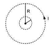
Let current I flow through circular loop of radius R. The magnetic field at the centre of loop \(B=\frac{\mu_0 I}{2 R}\)
As r << R the magnetic field can assumed to constant through entire area of inner loop magnetic flux linked with smaller loop.
\(\phi_{\mathrm{C}}=\mathrm{BA}=\frac{\mu_0 \mathrm{I}}{2 \mathrm{R}} \pi r^2\)
\(\phi=\mathrm{MI}\)
\(\mathrm{M}=\frac{\phi}{\mathrm{I}}=\frac{\mu_0 \pi r^2}{2 \mathrm{R}}\)
OR
Magnetic field produced on the wire (carrying current I2) due to I1 will be
Force acting at / length is
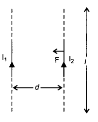
F = \(\mathrm{F}=\mathrm{I}_2 l \mathrm{~B}\)
\(\mathrm{F}=\frac{\mu_0 \mathrm{I}_1 \mathrm{I}_2 l}{2 \pi d}\) towards I1
If I = 1 m, d = I1, b = I2 = I and F = 2 × 10⁻⁷ N
⇒ I =1 A
So one ampere is defined as the current, which when maintained in two parallel infinite length conductors, held at a separation of one metre will produce a force of 2 × 10⁻⁷ N per metre on each conductor.
![]()
Section – D
Case Study Based Questions:
Question 29.
Read the following paragraph and answer the questions that follow:
A semiconductor diode is basically a Pn junction with metallic contacts provided at the ends for the application of an external voltage. It is a two terminal device. When an external voltage is applied across a semiconductor diode such that p-side is connected to the positive terminal of the battery and w-side to the negative terminal, it is said to be forward biased. When an external voltage is applied across the diode such that n-side is positive and p-side is negative, it is said to be reverse biased. An ideal diode is one whose resistance in forward biasing is zero and the resistance is infinite in reverse biasing. When the diode is forward biased, it is found that beyond forward voltage called knee voltage, the conductivity is very high. When the biasing voltage is more than the knee voltage the potential barrier is overcome and the current increases rapidly with increase in forward voltage. When the diode is reverse biased, the reverse bias voltage produces a very small current about a few microamperes which almost remains constant with bias. This small current is reverse saturation current.
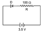
(i) In the given figure, a diode D is connected to an external resistance R = 100 Ω and an emf of 3.5 V. If the barrier potential developed across the diode is 0.5 V, the current in the circuit will be:
(a) 40 mA
(b) 20 mA
(c) 35 mA
(d) 30 mA
Answer:
(d) 30 mA
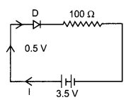
3.5 -0.5 = IR
3V =1(100)
I = 30 mA
(ii) In which of the following figures, the pn diode is reverse biased?
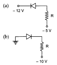
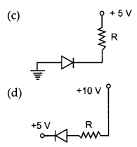
Answer:
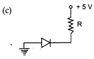
p side is connected to lower voltage i.e., ground n side is connected to higher voltage. Therefore, diode is reverse biased.
(iii) Based on the V-I characteristics of the diode, we can classify diode as:
(a) bilateral device
(b) ohmic device
(c) non-ohmic device
(d) passive element
OR
Two identical PN junctions can be connected in series by three different methods as shown in the figure. If the potential difference in the junctions is the same, then the correct connections will be:

(a) in the circuits (1) and (2)
(b) in the circuits (2) and (3)
(c) in the circuits (1) and (3)
(d) only in the circuit (1)
Answer:
(c) Non ohmic device as diodes do not follow Ohm’s law.
OR
(b) in the circuits (2) and (3)
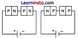
Both are forward biased in 2 both are revers biased in 3
(iv)
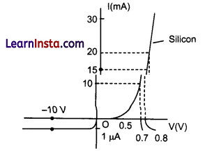
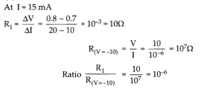
The V-I characteristic of a diode is shown in the figure. The ratio of the resistance of the diode at I = 15 mA to the resistance at V =- 10 V is:
(a) 100
(b) 106
(c) 10
(d) 10-16
Ans.
(d) 10-16
At I = 15 mA
![]()
Question 30.
Read the following paragraph and answer the questions that follow.
Types of Lenses and their combination:
A convex or converging lens is thicker at the centre than at the edges. It converges a beam of light on refraction through it. It has a real focus. Convex lens is of three types: Double convex lens, Plano convex lens and Concavo-convex lens.
Concave lens is thinner at the centre than at the edges. It diverges a beam of light on refraction through it. It has a virtual focus. Concave lenses are of three types: Double concave lens, Plano concave lens and Convexo-concave lens.
When two thin lenses of focal lengths f1 and f2 are placed in contact with each other along their common principal axis, then the two lens system is regarded as a single lens of focal length/and
If several thin lenses of focal length f1, f2,…..fn are placed in contact, then the effective focal length of the combination is given by
\(\frac{1}{f}=\frac{1}{f_1}+\frac{1}{f_2}+\ldots+\frac{1}{f_n}\)and in terms of power, we can write
P = P1 + P2 + …….. pn
The value of focal length and power of a lens must be used with proper sign consideration.
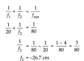
(i) Two thin lenses are kept coaxially in contact with each other and the focal length of the combination is 80 cm. If the focal length of one lens is 20 cm, the focal length of the other would be:
(a) -26.7 cm
(b) 60 cm
(c) 80 cm
(d) 30 cm
Answer:
(a) – 26.7 cm
(ii) A spherical air bubble is embedded in a piece of glass. For a ray of light passing through the bubble, it
behaves like a:
(a) converging lens
(b) diverging lens
(c) mirror
(d) thin plane sheet of glass
Answer:
(b) diverging lens
When a spherical air bubble is embedded in a piece of glass, the inside surface like a concave lens and as light passes from glass to air inside the cavity it will bend away from normal and hence incident ray will diverge like a concave lens or diverging lens.
(iii) Lens generally used in magnifying glass is:
(a) single concave lens
(b) single convex lens
(c) combination of convex lens of lower power and concave lens of lower focal length
(d) Plano concave lens
Answer:
(b) single convex lens
![]()
(iv) The magnification of an image by a convex lens is positive only when the object is placed:
(a) at its focus F
(b) between F and 2F
(c) at 2F
(d) between F and optical centre
OR
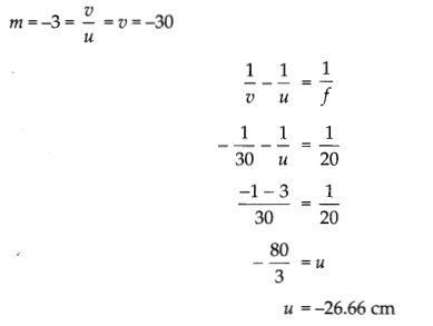
A convex lens of 20 cm focal length forms a real image which is three times magnified. The distance of the object from the lens is
{a) 13.33 cm
(b) 14 cm
(c) 26.66 cm
(d) 25 cm
Ans.
(d) between F and optical centre
OR
(c) 26.66 cm
Section – E
Question 31.
(i) Draw a ray diagram for the formation of image of a point object by a thin double convex lens having radii of curvature R1 and R2. Hence derive lens maker’s formula.
(ii) A converging lens has a focal length of10 cm in air. It is made of a material of refractive index 1.6. If it is immersed in a liquid of refractive index 1.3, find its new focal length.
OR
(i) Define a wavefront. How is it different from a ray?
(ii) Using Huygens’ construction of secondary wavelets draw a diagram showing the passage of a plane wavefront from a denser to a rarer medium. Using it verify Snell’s law.
(iii) In a double slit experiment using light of wavelength 600 nm and the angular width of the fringe formed on a distant screen is 0.1°. Find the spacing between the two slits.
(iv) Write two differences between interference pattern and diffraction pattern.
Answer:
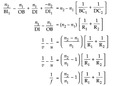
(i)
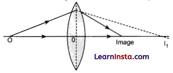
Step 1: The first refracting surface forms the image IT of the object O
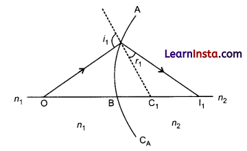
Step 2:
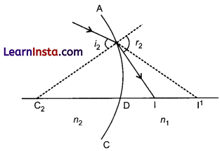
The image of object for first surface acts like virtual object for second surface.
First surface
Second surface
\(\frac{n_1}{\mathrm{DI}}+\frac{-n_2}{\mathrm{DI}_1}=\frac{n_2-n_1}{\mathrm{DC}_2}\)Adding (1) and (2)
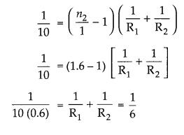
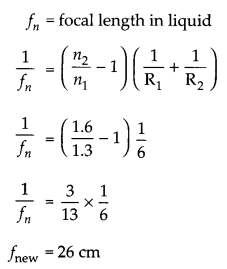
(ii) In air n1 = 1, f= 10 cm, n2 = 1.6
OR
(i) A wevefront is defined as a surface of constant phase.
(a) The ray indicates the direction of propagation of wave while the wavefront is the surface of constant phase.
(b) The ray at each point of a wavefront is normal to the wavefront at that point.
![]()
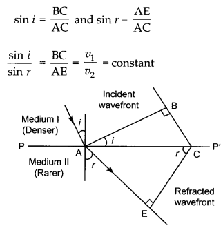
(ii) AB: Incident plane wave front and CE is refracted wave front.
(iv)
| Diffraction | Interference |
| Fringe width is unequal | Fringe width is usually equal. |
| Brightness or intensity of fringes is not same in diffraction pattern. | Brightness of fringes is usually same in case of interference pattern. |
| Fringe spacing is non-uniform | Fringe spacing is uniform. |
| The contrast between maxima and minima is poor | The contrast between maxima and minima is good. |
Question 32.
(i) Derive an expression for the capacitance of a parallel plate capacitor with air present between the two plates.
(ii) Obtain the equivalent capacitance of the network shown in figure. For a 300 V supply, determine the charge on each capacitor.
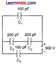
OR
(i) A dielectric slab of thickness ‘? is kept between the plates of a parallel plate capacitor with plate separation ‘d’ (t < d). Derive the expression for the capacitance of the capacitor.
(ii) A capacitor of capacity C1 is charged to the potential of V0. On disconnecting with the battery, it is, connected with an uncharged capacitor of capacity C2 as shown in the following figure. Find the ratio of energies before and after the connection of switch S.
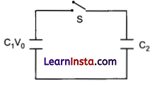
Answer:
(i) Derivation of the expression for the capacitance
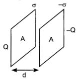
Let the two plates be kept parallel to each other separated by a distance d and cross-sectional area of each plate is A.
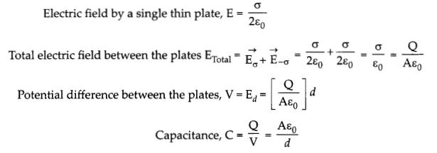
(ii)
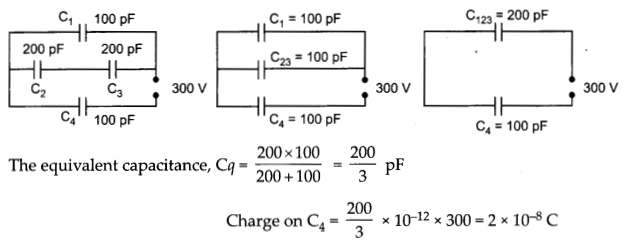
Potential difference across, C4 = \(\frac{200 \times 10^{-12} \times 300}{3 \times 100 \times 10^{-12}}=200 \mathrm{~V}\)
Potential difference across, C1 = 300- 200 = 100 V
Charge on, C1 = 100 × 10-12 × 100 = 1 × 10⁻⁸C
Potential difference across C2 and C3 series combination = 100 V
Potential difference across C2 and C3 each = 50 V
Charge on C2 and C3 each = 200 × 10-12 × 50 = 1 × 10⁻⁸C.
OR
(i) Derivation of the expression for capacitance with dielectric slab (t < d)
Let A is the area of the two plates of the parallel plate capacitor and d is the separation between them. A dielectric slab of thickness t < d and area A is kept between the two plates. The total electric field inside the dielectric slab will be,
Where E is the opposite field developed inside the slab due to polarisation of slab. Total potential difference between the plates,
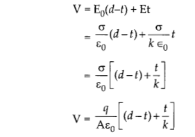
(ii)
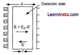
where q is the charge on each plate.
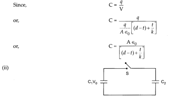
Before the connection of switch S,
Initial energy,
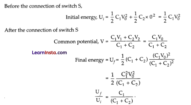
![]()
Question 33.
(a) Draw graphs showing the variations of inductive reactance and capacitive reactance with frequency of applied a.c. source.
(b) Draw the phasor diagram for a series LRC circuit connected to an AC source.
(c) When an alternating voltage of 220 V is applied across a device X, a current of 0.25 A flows which lags behind the applied voltage in phase by π/2 radian. If the same voltage is applied across another
device Y, the same current flows but now it is in phase with the applied voltage.
(i) Name the devices X and Y.
(ii) Calculate the current flowing in the circuit when the same voltage is applied across the series -s combination of X and Y.
OR
(a) A series LCR circuit is connected to an ac source. Using the phasor diagram, derive the expression for the impedance of the circuit.
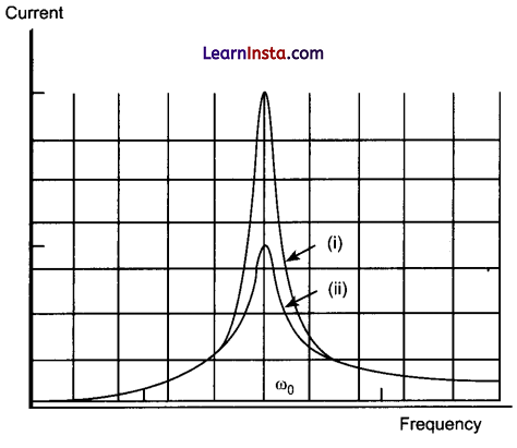
(b) Plot a graph to show the variation of current with frequency of the ac source, explaining the nature of its variation for two different resistances R1 and R2 (Rx < R2) at resonance.
Answer:
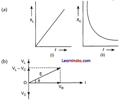
(c) (i) In device X, Current lags behind the voltage by \(\frac{\pi}{2}\), X is an inductor.
In device Y, Current in phase with the applied voltage, Y is resistor.
(ii) We are given that
For device X :
\(0.25=\frac{220}{X_L} \Rightarrow X_L=880 \Omega\)
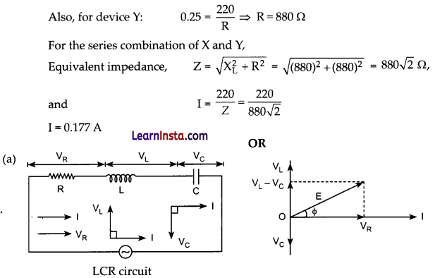
E = E0 sin ωt is applied to a series LCR circuit. Since all three of them are connected in series the current through them is same. But the voltage across each element has a different phase relation with current. The potential difference VL, Vc and VR across L, C and R at any instant is given by
VL = IXL, Vc = IXC and VR = IR,
Where I is the current at that instant.
VR is in phase with I. VL leads I by 90° and Vc lags behind I by 90°, so the phasor diagram will be as shown. Assuming VL > Vc, the applied emf E which is equal to resultant of potential drop across R, L and C is given as

Or

![]()
(b) The curve (i) is for Rj and the curve (ii) is for R2.
